

Summary
Transcatheter aortic valve implementation requires multimodality imaging during procedural planning, intraprocedural implantation and optimization, and long-term follow-up. A variety of options are available and each modality has its own strengths and limitations. The present article focuses on the progress in this area and the new technologies that are being developed.
- transcatheter aortic valve implantation
- aortic stenosis
- valvular disease
- aortic annulus
- EchoNavigator System
- echocardiography
- computed tomography
- 3D imaging
- 4D imaging
- CoreValve
Transcatheter aortic valve implantation (TAVI) is an important treatment option for inoperable and high-surgical-risk patients with symptomatic severe aortic stenosis; however, the safety and success of implantation are highly dependent on in-depth knowledge of the anatomy of the aortic root, proper patient selection, and accurate imaging and measurement [Kasel AM et al. JACC Cardiovasc Imaging. 2013]. Francesco F. Faletra, MD, Fondazione Cardiocentro Ticino, Lugano, Switzerland, discussed the anatomy of the aortic root and where and how to measure the aortic annulus in the TAVI era.
The aortic root is a complex structure that connects the heart to the systemic circulation. It is composed of several distinct entities, including aortic valve leaflets and their attachments to the aortic wall (the annulus), the sinuses of Valsalva, 3 interleaflet triangles, the sinotubular junction, and the ventriculoarterial junction. The dynamic and well-coordinated rhythm of these subunits during the cardiac cycle is responsible for specific flow characteristics, coronary perfusion, and left ventricular function.
The normal aortic root is round during systole and typically elliptical during diastole [Kenny C, Monaghan M. Heart. 2014; Zamorano JL et al. Eur Heart J. 2014; Muraru D et al. Eur Heart J Cardiovasc Imaging. 2012]. If the elliptical shape is not properly accounted for on imaging, errors in measurement can lead to paravalvular regurgitation as a result of an ill-fitting prosthesis [Faletra FF et al. Real-Time 3D Interventional Echocardiography. 2014].
There are significant challenges in measuring an accurate aortic annulus such as an irregular shape of the annulus, differences of the plane in which the leaflets insert, and calcification of the valve. Prof Faletra suggests that when measuring the annulus for purposes of TAVI, the correct references are circumference and area rather than diameter.
All cardiac interventional procedures require echographic monitoring, so integration of imaging and communication between the echographer and cardiologist in the catheterization laboratory is important. Julien Ternacle, MD, Henri Mondor Hospital, Créteil, France, discussed the EchoNavigator System, which combines live transesophageal echocardiography (TEE) and fluoroscopy images in real time in the same system. Because the TEE probe position and orientation are automatically tracked in the x-ray image, the echo and x-ray images now move in sync when the C-arm is repositioned. The system provides a live fusion between these two modalities on a same view. In addition, markers placed on strategic points within the echo image automatically appear on the x-ray for context and guidance. The TEE field of view (cone) is also displayed as an outline for additional reference. Up to 3 different echo views can be shown simultaneously.
In a typical quad-screen display, the side panel is used for navigation, to capture a screen image and to reset the views. The x-ray view displays the live image from the x-ray system combined with the echo probe cone after synchronization. The registration view is always visible in a floating window to control the connection between x-ray and TEE. The C-arm view displays echo images according to the orientation of the C-arm. The echo view displays the image determined by the sonographer. The free view displays the echo image determined by the interventional cardiologist from a table with all the usual options (2 and 3D, Doppler). Its initial orientation is the same as the C-arm view, but the 3D volume can be rotated, rolled, or cropped.
Dr Ternacle believes that the ability to add, edit, and delete markers is the most innovative aspect of the EchoNavigator as these functions increase accuracy and provide additional procedural guidance. The system has been used for left atrial appendage closures, atrial septal defect closures, and mitraclip placement [Sündermann SH et al. EuroIntervention. 2014]. A reduction of the radiation dose could be expected with this system, but future studies should confirm it.
Although a somewhat common procedure, several concerns remain with respect to TAVI. These include conduction abnormalities, aortic regurgitation, and stroke, as well as less frequent but severe complications such as annular rupture and coronary obstruction. The solution to these concerns can be found by looking into individual aspects of the procedure such as the device, the actual procedure, and procedural planning. Peter Mortier, FEops, Ghent University, Ghent, Belgium, discussed how combining preoperative computed tomography imaging with advanced finite-element computer simulations may help to improve TAVI outcomes by predicting how a specific device will interact with a specific patient.
The planning of TAVI is currently based on using imaging to evaluate the aortic anatomy to determine the annular dimensions and thus the appropriate device for each patient. However, measurements using transthoracic echocardiography, TEE, and multislice computed tomography (MSCT) are not identical [Messika-Zeitoun D et al. J Am Col Cardiol. 2010]. In addition, in some patients the device may not fully expand and/or the aortic root may be deformed. Finally, a variety of devices are now available and it is highly unlikely that any single one device will best serve all patients; thus, imaging plays an important role in individualizing the choice of valve used in TAVI.
According to Dr Mortier, imaging alone provides limited insight into the risk of complications. He believes that the solution to choosing the correct device is a patient-specific computer simulation, which uses a 3D computer model of the patient’s aortic root. The model incorporates the mechanical behavior of different tissue regions and a 3D computer model of various transcatheter aortic valves. It also incorporates the mechanical behavior of the stent frame to predict the valve morphology and native leaflet displacement post-TAVI using finite-element analysis and valve function post-TAVI with the use of computational fluid dynamics. This approach has the advantage of providing preoperative insights into the feasibility of and risk associated with TAVI before the procedure, facilitating the choice of the optimal device size and type for each patient, improving patient selection.
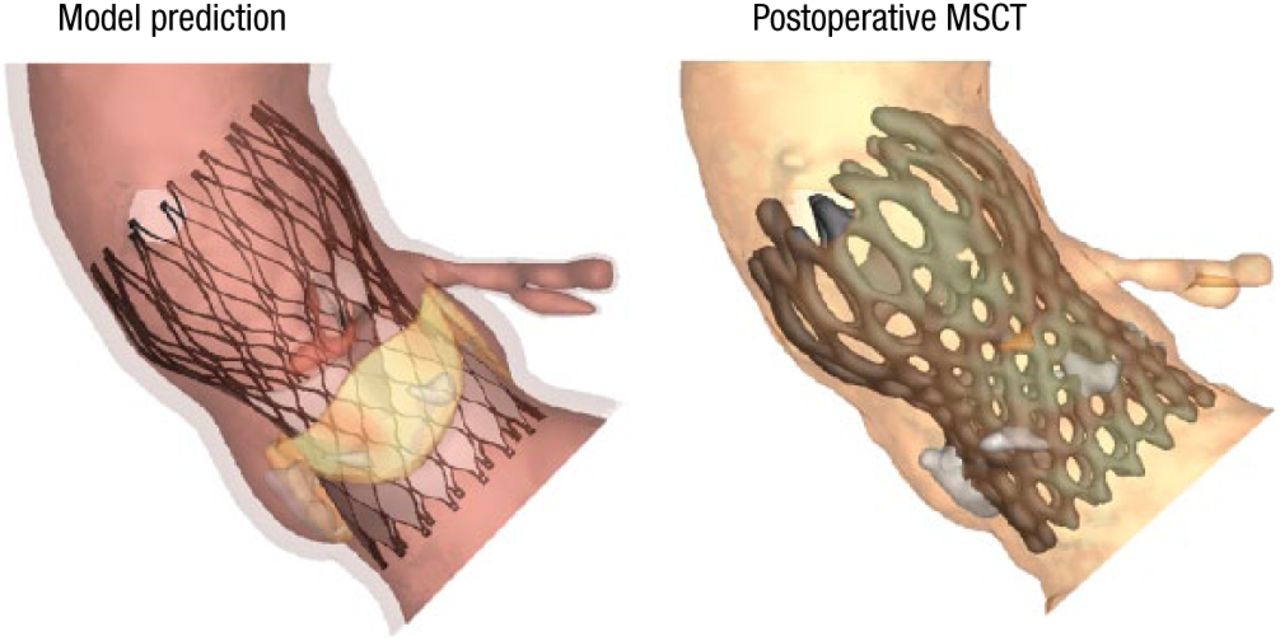
Comparisons between the model predictions and postoperative imaging (eg, MSCT scans and aortography) show good correlation in morphology (Figure 1), calcium displacement, and valve function, said Dr Mortier.

Valve Morphology: Model vs Postoperative MSCT
MSCT, multislice computed tomography.
Reproduced with permission from P Mortier, MD.
Dr Mortier concluded by noting that additional studies are needed to further assess this methodology and continuing work is needed so that clinicians go beyond just measuring the anatomy when planning TAVI.
The final presentation in this session concerned the use of various imaging modalities in TAVI. Peter P.T. de Jaegere, MD, Erasmus MC, Rotterdam, The Netherlands, discussed the value of 3D and 4D imaging for planning, guidance, and evaluation before, during, and after TAVI.
In the catheterization laboratory, rotational angiography (R-angio) with dedicated motion compensation software (prototype) can be used to create 3D images similar to MSCT. The images are available for analysis within a minute after acquisition and may be used for on-line evaluation of annulus (sizing) but more importantly outcome and in particular the etiology of paravalvular regurgitation. Schulz CJ and colleagues found that R-angio of the left ventricle allowed precise measurement of the aortic root and annulus and was feasible for sizing at the time of TAVI [Eur Heart J Cardiovasc Imaging. 2014].
Although R-angio allows for multiple angiographic views, motion artifacts resulting from poor temporal resolution severely degrade 3D images [Schultz CJ et al. Eurointervention. 2014]. Acquiring R-angio during rapid ventricular pacing effectively causes ventricular standstill and reduces motion artifacts; however, methods to correct for cardiac motion without the need for rapid pacing would be beneficial.
In a recent study, Schultz evaluated the image quality obtained with R-angio motion-compensated reconstruction of the implanted Medtronic CoreValve frame and the clinical and anatomical correlates of 3D frame geometry [Schultz CJ et al. Eurointervention. 2014]. CoreValve frame geometry was evaluated with both MSCT and R-angio at the level of the inflow, nadir of the leaflets, central coaptation point, and commissures. The native aortic annulus dimensions were measured at the nadirs of the 3 leaflets. Sizing ratio, prosthesis expansion, and frame ellipticity were also assessed. Good-quality 3D reconstructions were obtained in 84% of patients, and failure was predictable prior to reconstruction in 6 of the remaining patients.
In a recently published case study, R-angio with motion correction was used to identify the cause of balloon underexpansion in a patient with aortic regurgitation following TAVI [Rodriguez-Olivares R et al. JACC Cardiovasc Interven. 2014].
In Prof de Jaegere’s opinion, the planning of TAVI and the imaging evaluation during the procedure requires both 3D and 4D imaging. On-line 3D and 4D imaging with R-angio is feasible and has the advantages of being able to be performed in the catheterization laboratory, requires no other imaging modalities, and provides immediate insight into the results of TAVI. R-angio with motion compensation remains a work in progress, and continued improvement is needed in order to correct for motion artifacts and demonstrate the effectiveness of this strategy with multiple types of valves.
- © 2014 SAGE Publications
Tools


Table of contents
Cited By...
- No citing articles found.