

Summary
This article discusses the role of imaging before, during, and after TAVI, as well as an overview of the imaging techniques that are used to evaluate heart failure.
- interventional techniques & devices
- heart failure
- imaging modalities
- cardiac imaging techniques
Imaging in TAVI
Aortic valve replacement is an invasive procedure, with considerable mortality and morbidity, especially in more fragile patients. Transcutaneous aortic valve implantation (TAVI), in which a bioprosthetic valve is transported to the heart through a small incision in the groin, has evolved as an alternative for valve replacement in high-risk patients. Peter De Jaegere, MD, Erasmus Medical Center, Rotterdam, The Netherlands, discussed the role of imaging before, during, and after TAVI. The discussion focused on using multislice computer tomography (MSCT) for the evaluation of the aortic root within view to select patients with suitable anatomy and to guide valve sizing.
Sizing and positioning are considered the key parameters for correct aortic valve placement. Incorrect sizing may result in adverse outcomes, including paraprosthetic regurgitation and asymmetrical expansion, which may impair prosthesis durability. In the case of severe sizing errors, device embolization or aortic root rupture may occur. Prof. De Jaegere described how it is possible to take an anatomical approach to sizing by using MSCT to define the aortic annulus and structures of the aortic root. These landmarks are then used as references to describe the same structures for measurement on a 3-D MSCT dataset by setting up orthogonal cut-planes, including one that is axial to the aortic annulus [Schultz C et al. Euro Intervention 2010].
For correct annulus definition, a 3-D imaging modality that offers enough spatial and temporal resolution, as well as accurate quantification of the aortic root, is needed. Transthoracic echocardiography (TTE), according to Prof. De Jaegere, may not meet this requirement, because different measurements are obtained, based on the section that is transected.
Prof. De Jaegere noted that the right method for sizing is still lacking. Manufacturers have specific size recommendations for their prosthetic devices. However, sizing may be more complex than the approach that is currently recommended by manufacturers. The prosthesis and recipient anatomy are not always the same. For example, the device is circular, whereas the aortic annulus often is elliptic, and there are leaflets and sinuses that need to be considered. Thus, off-label implantation using revalving systems (eg, Core Valve ReValving System) for TAVI is common.
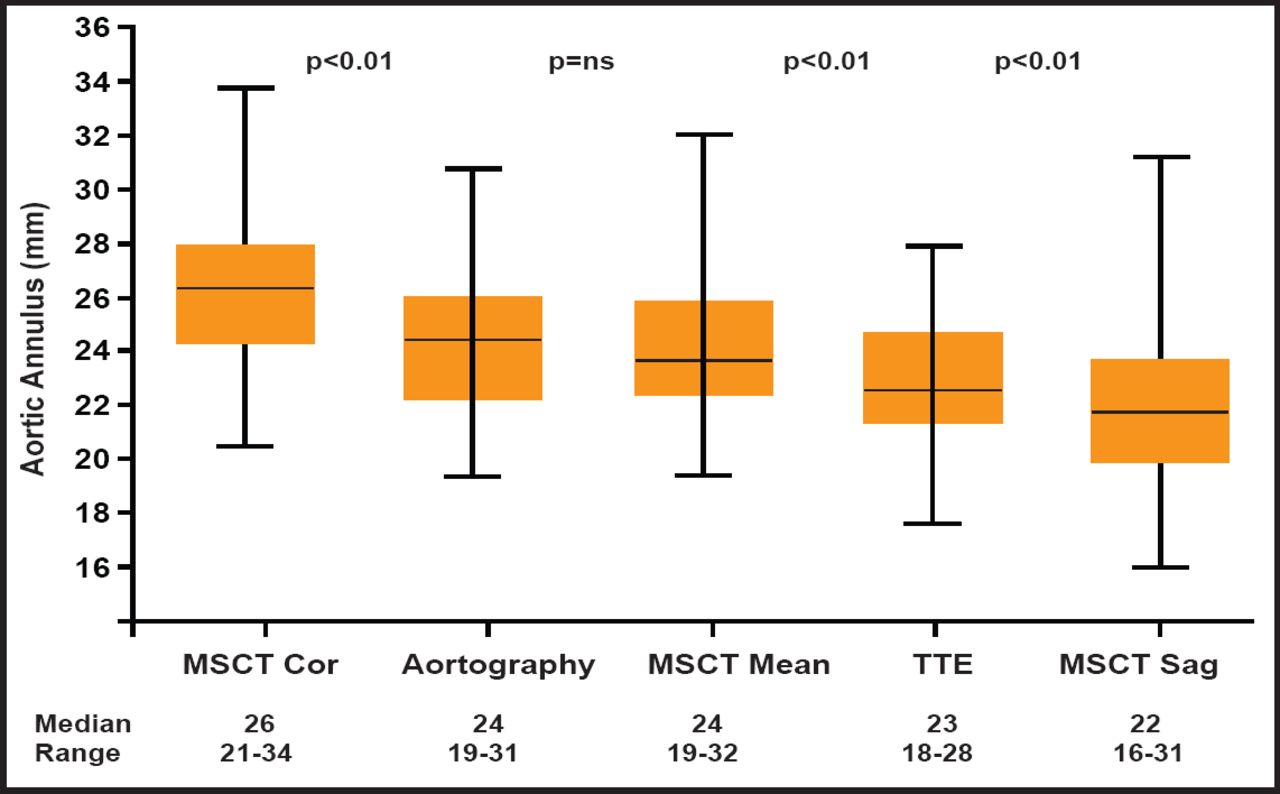
The variability of annulus assessment using TTE appears to be greater than that achieved with MSCT. One study reported interobserver differences with TTE to be between −5 mm to −5 mm, whereas interobserver variability with MSCT coronal and sagittal measurements in the same study were between 2 mm and −2 mm and 3 mm and −3 mm, respectively [Tzikas A et al. Catheter Cardiovasc Interv 2010]. An overview of the differences in aortic annulus (mm) values that were obtained using these different imaging techniques in the 70 patients who were studied is shown in Figure 1. The values that were observed were frequently outside those recommended by the manufacturers (23 to 29 mm). Thus, depending on the measurement used in practice, the degree of agreement with industry standards can vary substantially. Differences between observers regarding annulus size and fit with the prosthetic device can also vary a great deal, depending on which imaging modality is employed. However, it should be pointed out that there was no difference that was observed in the procedural success rate between on-label and off-label groups. The frequency of angiographic moderate-severe aortic regurgitation, postimplant dilatation, and implantation of a second valve was similar between the two groups.

Aortic Annulus Values.
Reproduced with permission from John Wiley & Son's. Tzikas A et al. Assessment of the aortic annulus by multislice computed tomography, contrast aortography, and trans-thoracic echocardiography in patients referred for transcatheter aortic valve implantation. Catheter Cardiovasc Interv 2011;77(6):868–875.
Prof. De Jaegere's cath lab is experimenting with rotational angiography as a surrogate for MSCT for sizing. Using contrast angiography only, the technique shows promise as a potential 3D annulus measurement and evaluation tool that can be used during TAVI. The annulus is defined at the nadir of 3 leaflets. Software is being developed to analyze the images.
New types of software are being developed, based upon 3-D overlay and real-time 2-D overlay using consistent anatomical location as landmarks that may be useful in device delivery. More work is required to perfect this technique. In the future, 4-D imaging and rotational angiography may be employed to evaluate placement of the TAVI devices. Though these modalities are available now, they are not used clinically yet.
Prof. De Jaegere believes the MSCT should be the gold standard for evaluating and planning access to annulus for TAVI. Online guidance can be done with x-ray and TEE, but better software needs to be developed to assist in this process. Fortunately, the future tools that are under investigation hold great promise for evaluating correct TAVI placement. As TAVI is assuming a major role in the routine management of patients with aortic stenosis, improved tools for the placement of these devices will take on added importance.
Imaging in Heart Failure
Heart failure (HF) remains one of the most common causes of hospitalization and death in developed countries, with prevalence rates predicted to increase in line with population aging. Mohamed Ayman Abdel Hay, MD, Alexandria University, Alexandria, Egypt, presented an overview of the imaging techniques that are used to evaluate HF, including methods to quantify and monitor ventricular performance, establish a diagnosis, stratify risk, and evaluate complications.
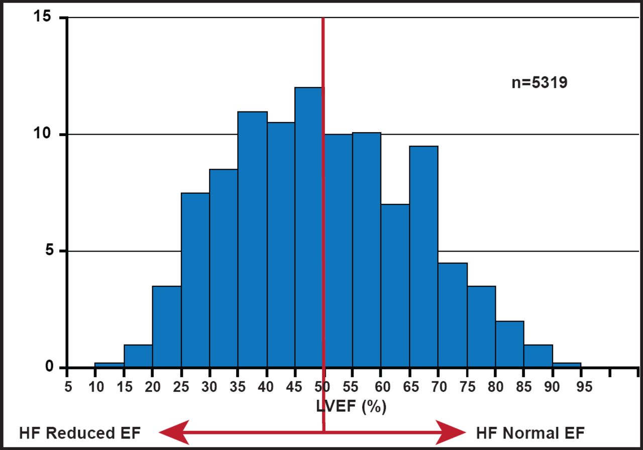
There are two important keys to determining HF severity: ejection fraction (EF) and left ventricular (LV) filling pressure. About half of patients who are admitted to the hospital with HF have a reduced EF, while the others have normal EFs (Figure 2). There are a variety of imaging tools that are available for use in distinguishing these patient groups. As an imaging tool, echocardiogram (ECHO) has the advantages of being widely available, relatively low in cost, portable, safe, and patient-friendly. It can also be used at the bedside in unstable patients. 2-D ECHO can be used to detect LV volumes and EF, and is capable of displaying cross-sectional slices of the beating heart, including the chambers, valves, and the major blood vessels that exit from the left and right ventricle. However, alignment of the imaging planes in the correct axis is critical and can be constrained by limited imaging windows. Use of contrast ECHO can improve accuracy. ECHO functionality can be improved further with 3-D ECHO, which can be used to obtain accurate measurement of LV filling pressure. The ability to trace the LV border in multiple long-axis planes (and to crosscheck against short-axis images) provides an accurate means of measuring LV volumes, even in irregularly shaped ventricles.

LVEF Distribution in Hospitalized HF.
Reproduced with permission from MAA Hay, MD.
ECHO can be used to calculate the left atrial (LA) volume, an important marker of LV diastolic filling. “Indexed LA volume should become routine measure,” said Prof. Hay, “since it reflects elevated LV filling pressure and is a strong predictor of outcome.” ECHO can also help to characterize mitral regurgitation mechanism, such as between predominantly posterior wall motion abnormalities and LV enlargement with diffuse wall motion abnormalities, for which the treatment is very different [Marwick TH et al. Circ Cardiovasc Imaging 2008].
Strain Doppler echocardiography (SDE) is a new tool that allows quantitative assessment of segmental myocardial contractility and may be helpful in the assessment of patients with HF. 2D strain may also be measured noninvasively with tagged magnetic resonance imaging but the most widely used quantitative package has been validated only for short-axis images. Tissue-velocity strain has the benefit of high temporal resolution but is angle-dependent, may be limited by signal noise, and is difficult to perform in the short axis, especially if the LV wall is thinned. Various newer iterations of 2D strain are available; these methods are simpler to use than the alternatives and independent of angle, but they are dependent on good image quality and have lower temporal resolution than tissue velocity strain. Determination of the presence or absence of scar tissue and the correct placement of LV leads are essential for good results. This is an important distinction, since cardiac resynchronization (CRT) therapy does not reduce LV dyssynchrony in patients with transmural scar tissue in the posterolateral LV segments [Bleeker GB et al. Circulation 2006].
Cardiac MRI (3D ECHO and cMRI) is useful for determining ventricular function, cardiac morphology, vasculature and perfusion, and viability and metabolism. It can also be used to detect myopathies and intraventricular thrombus. It is a very sensitive tool for accurate determination of LV morphology (shape, mass, volumes, and EF) and ventricular function. It is also a useful tool for determining the relation between total scar burden and response to CRT. Total scar burden, assessed using contrast-enhanced MRI (ceMRI), is an important factor that influences response to CRT.
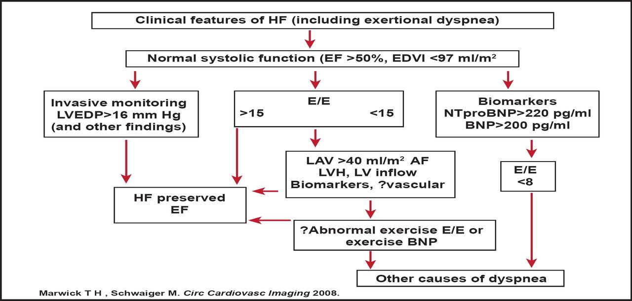
Prof. Hay outlined a protocol for incorporating imaging parameters in the diagnosis of HF with preserved EF (Figure 3). The protocol is noteworthy, as it permits exertional dyspnea (not hospital admission with HF) to be the index symptom, places LV filling estimation by ECHO as a central feature, and permits sequential testing of those with ambiguous results. Future iterations may incorporate vascular dysfunction as a corroborative finding or assess exercise response before concluding that there is no cardiac explanation for dyspnea.

LV Filling Estimation by ECHO is a Central Feature in Identifying HF with Preserved EF.
BNP=type B natriuretic peptide; EDVI=end-diastolic volume index; E/E'=ratio of transmitral to myocardial velocity; LVEDP=left ventricular diastolic pressure; LAV=left anterior volume; LVH=left ventricular hypertrophy; HF=heart failure; AF=atrial fibrillation.
Reproduced with permission from MAA Hay, MD.
There are etiological issues to consider in HF imaging. The etiology of HF may have an independent cofactor and be subject to a promoter (increases expression) to cause disease. The exclusion of coronary etiology and assessment of viability have been the source of most attention until recently. Increasingly, this is being matched by consideration of noncoronary etiologies, although this application has been hampered by limited specific therapeutic indications. Exclusion of coronary artery disease (dependent upon age, setting) is the first step in the confirmation of HF diagnosis and functional assessment. Scar distribution on ceMRI is an important determinant of which noncoronary etiology that the clinician is facing
Prof. Hay concluded that future developments in the care of advanced heart disease, including stem cell therapy, device therapy to control remodeling, and percutaneous valve interventions, as well as the need to identify subclinical heart disease, are likely to expand the use of imaging.
- © 2011 MD Conference Express
Tools


Table of contents
Cited By...
- No citing articles found.